Point Indicators
 |
Over the years VR employed quite a few different types of devices to indicate which way points were laying. In interlocked 2 position signalled installations the theory went that every signalled move had to indicate the track to be taken, either by means of the fixed signals: home, disc or dwarf, or in the case of a disc that applied to two or more tracks, by means of point indicators. Later types introduced on an ad hoc basis were used to indicate the position of mainline points and needed to be viewable from a much greater distance than the first, and possibly oldest type shown below.
Point indicator assembly diagram |
||||||||||||
 |
|||||||||||||
 |
|||||||||||||
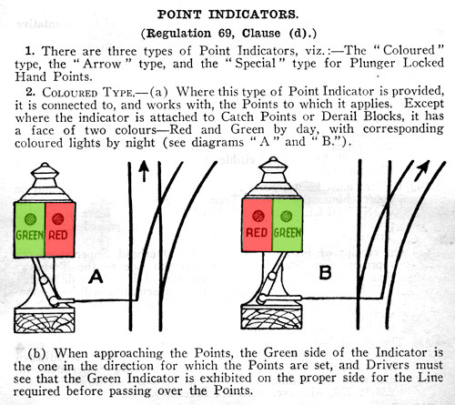
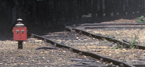
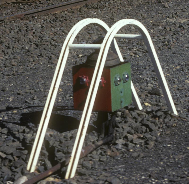
| This type was often called "box type" point indicators in later times. As described at right, the green half of the box or green light by night indicated the direction the points were set for. Personally I found these type all but useless to use an an engineman as you could see the actual point blades well before you could see the point indicator. Although not generally used at 3 position locations they were often used at switch locked sidings as shown below at Sunshine Standard Gauge loop. |
|||||||||||||
 |
|||||||||||||
 |
|||||||||||||
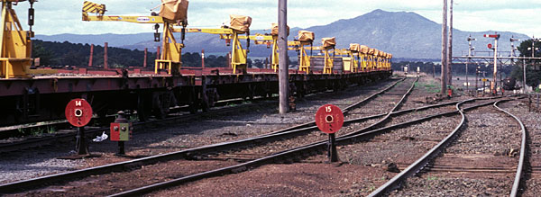
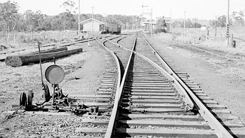
| This arrangement at Ararat was interesting. Disc 14 only applied to moves when the points were lying to the right for moves to the mainline, moves up the dead end did not require the disc. So a driver would have to stop at the disc if the point indicator was in the position showing but merrily trundle past the disc if the green on the point indicator was on the left. | |||||||||||||
|
|
|||||||||||||
 |
|||||||||||||
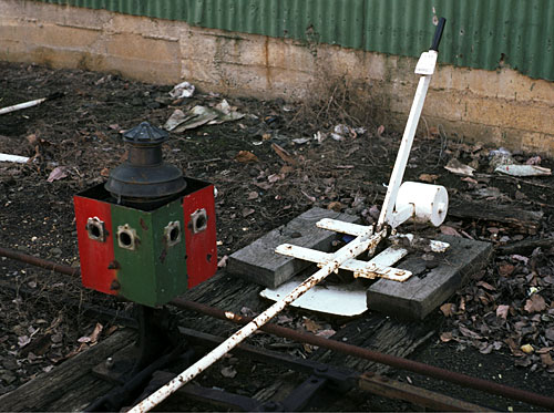
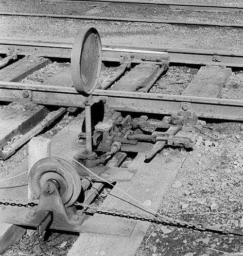
| Close up of a standard box type point indicator (missing its lenses) near the showgrounds. The small plate attached near the top of the point lever, had the words "NOT WIRED" meaning that the road that these points took you into had no overhead wire. 1980 | |||||||||||||
|
|
|||||||||||||
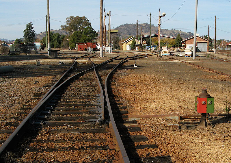
ABOVE: Box type point indicator at Wodonga, 2005
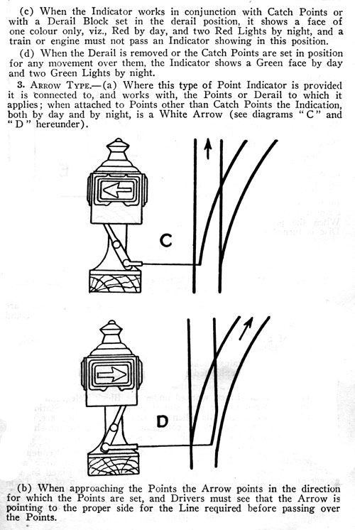
Arrow type Point Indicators
 |
 |
||
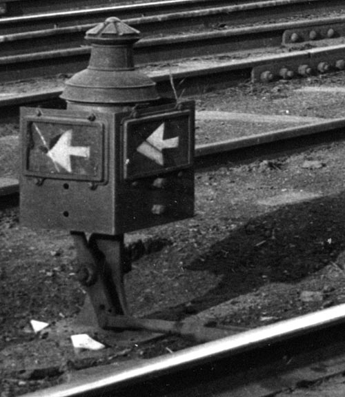
| The arrow type worked in a similar way to the coloured or box type but displayed which route the points were laying by means of arrows. This type was no longer in use prior to 1953, probably because of the maintenence required if the glass arrow plate was broken. | |||
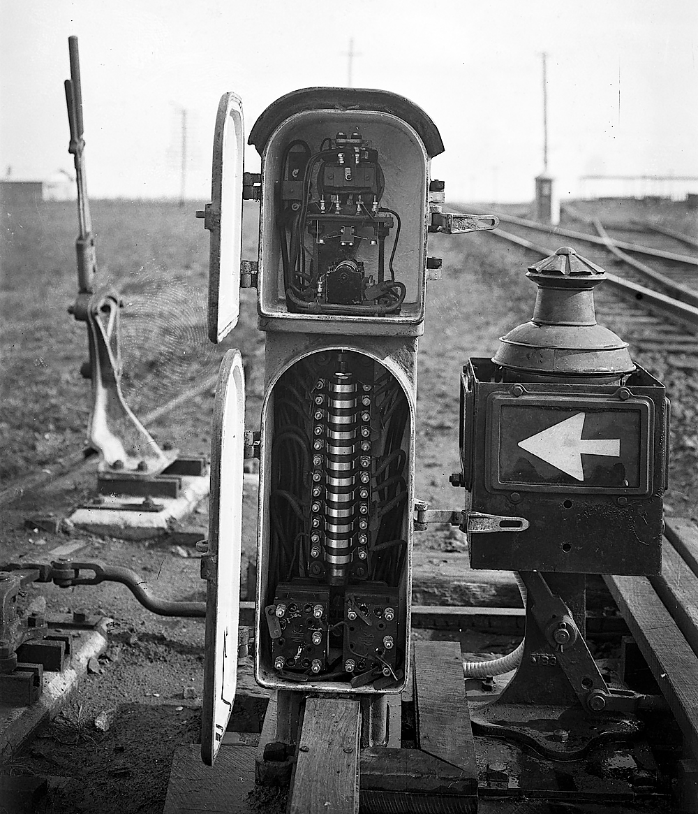
ABOVE: Arrow type point indicator (and electric switch lock) at Drome loop circa 1928
Catch point indicators
 |
 |
|||
 |
||||
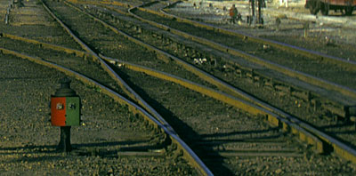
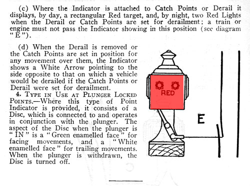
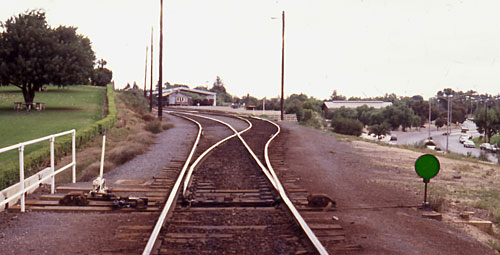
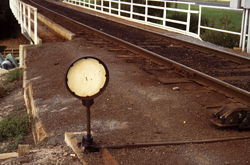
| Catch points are used to protect against a vehicle running from a yard track onto a running line. An open catch point is designed to derail a vehicle before it gets to a running line.The indication that the catch points were closed was with a full green face as shown at left. The white rails over the indicator at left afforded a measure of protection. | ||||
Plunger indicators
 |
|||||||||
| Plunger indicators were, strictly speaking, not point indicators. On mainline points at locations that were not fully interlocked, plunger locking was usually employed. Plunger locking was a crude, cheap form of interlocking that ensured the points were locked before the home signal could be placed to the proceed position. Although the use of plunger locking was quite widespread the use of plunger indicators was quite rare, in fact it appears that these indicators were never much more than a test. Because they had no light indication at night their usefullness was probably negligible. When the plunger was in a green disc was displayed (safe to run over the points) for facing moves and a white disc displayed for trailing moves, if the plunger was out the disc was turned to the side. Of particular concern at a plunger locked location was that the points not be run through in the trailing direction with the plunger in as this would result in damage to the plunger locking. The photo below shows the plunger indicator at Mildura, (the disc has been slightly colourised for clarity) It is assumed that the indicator was placed on the "wrong side" for sighting purposes. |
|||||||||
|
Photos above and below at Nyora, late 1970's courtesy Peter J. Vincent
|
|||||||||
 |
|||||||||
 |
|||||||||
 |
|||||||||
| This photo shows the white back of the indicator which indicated to a train that would trail through the points that the plunger was "in" Photo at Mildura, courtesy Chris Wurr |
|||||||||
Double Wire Control switchstands
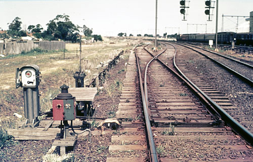
Double wire control of points and signals was not in widespread use in Victoria with Dandenong to Warragul and Gheringhap to Warrenheip lines being the main installations. They allowed points to be controlled from a greater distance from a signalbox than was possible with the customary point rods. At most Double Wire Control locations only one home arrival signal was provided so of course information as to which track the points were lying for had to be provided, this was acheived by the switchstand shown below.
More information on Double Wire Control can be found on Andrew Waugh's website
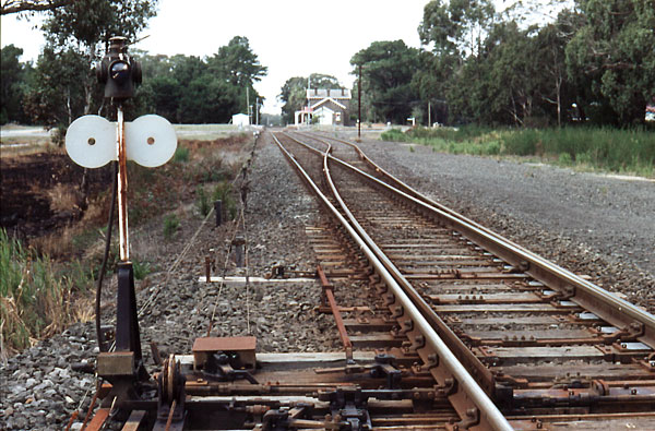
ABOVE: The white discs for straight moves. down end of Lal Lal. (photo courtesy Chris Wurr.)
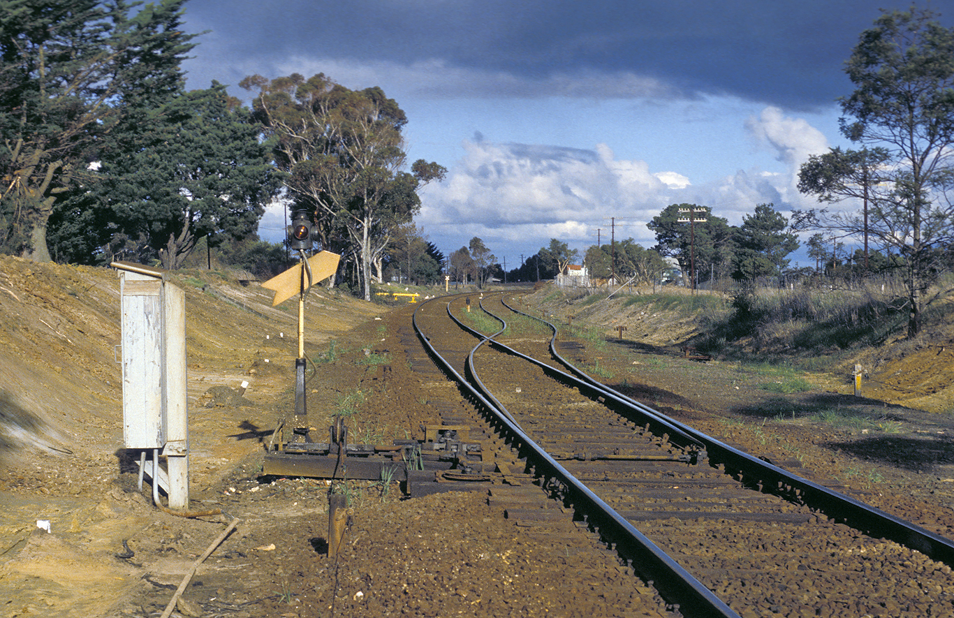
BELOW: The yellow arrow that indicated a move into the diverging track. (official VR photo)
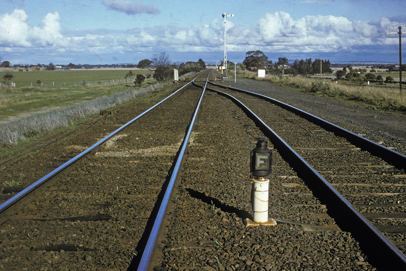
BELOW: As there were no home departure signals on this system a Fouling Point indicator was provided to indicate to the driver the point at which he could draw his train up to without fouling the other line. (official VR photo)