 |
||||
|
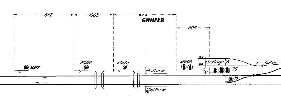
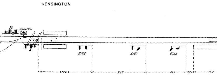
Three Position Signals Three position signals were introduced as part of the suburban electrification program. They permit trains to follow at much closer intervals than was previously possible, a side benefit was the abolition of many signal boxes. There are four types of 3 position signals
First of all the term "three position signals" is actually a meaningless term as it simply refers to the number of positions a single arm, or light, can display. Three position signals always need two arms or lights to display their aspects (except in the case of dwarf signals) and in Victoria a total of 6 aspects can be displayed by the combination of the two lights (7 if low speed aspects are included) Interlocked 2 position signals told a driver exactly which track the points were set for and this convention was carried over to 3 position signals at first. As introduced in 1915, the top arm or light told the driver the points were set for the straight and the bottom arm or light told the driver the points were set for the diverge. In 1918 this convention was abandoned with the introduction of 3 position signals between Newmarket and Kensington. It is important to understand that 3 position home and automatic signals require 2 lights to display their indications and that aspects and their meanings are identical for both home and automatic signals.
Thus, VR 3 position signals are purely speed signals, they do not normally convey information about the route to be taken. Of all the 3 position signals in Victoria only a very small number actually indicate the route to be taken without the use of route indicators, this is why the ad hoc use of route indicators is so widespread. |
||||
 |
||||
Identifying 3 position home and automatic signals
 |
 |
|
|
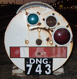
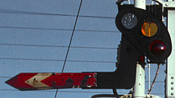
Home signals are identified by the 2 lights being vertical.
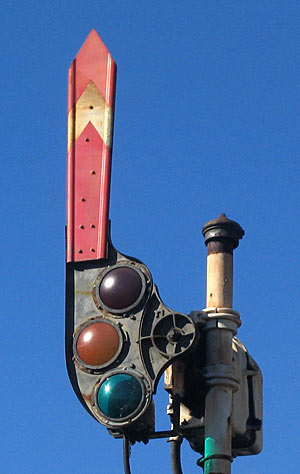
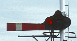
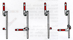
A semaphore home signal was identified by a red square ended arm |
Automatic signals are identified by the 2 lights being staggered.
A semaphore automatic signal was identified by a red pointed arm |
|
 |
 |
|
I will first go through all of the 3 position aspects and indications and then explain how they are used with diagrams. In signalling terms an ASPECT is the Appearence of the signal. An INDICATION is the information conveyed by the Aspect. |
 G/R
G/R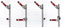
 Y/R
Y/R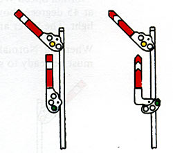
 Y/G
Y/G
 R/G
R/G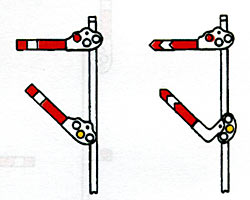
 R/Y
R/Y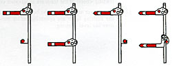
 R/R
R/R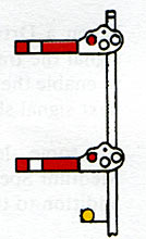
 R/R/Y
R/R/Y